
What Does Qmax Mean in the Context of BS EN 12845?
by Andrew Cowan
In the world of fire protection engineering, automatic sprinkler systems play a critical role in saving lives and property. Their success lies in their ability to detect and control fires quickly, limiting fire growth until emergency responders arrive. But for these systems to function as intended, two key elements must be properly designed: water density and duration of discharge.
Water density refers to the volume of water applied over a given area, typically measured in millimetres per minute (mm/min) or litres per minute per square metre (l/min/m²) in the UK. This specification ensures that a sufficient amount of water reaches the fire-affected area to absorb heat, lower the temperature of burning materials and prevent the fire from spreading to other parts of the building. If the water density is too low, it may evaporate before it can effectively cool the fuel, rendering the system ineffective.
Equally important is the duration for which the sprinkler system must maintain its flow rate. The system must be capable of sustaining this flow long enough to control the fire until it is either extinguished by the fire service or burns itself out in a controlled manner. Without sufficient duration, the fire could re-ignite or spread after an initial period of control. Both parameters – density and duration – are regulated by standards such as BS EN 12845, the European standard for the design, installation and maintenance of fixed fire sprinkler systems.
Among the various technical terms associated with hydraulic design in BS EN 12845, one critical concept is Qmax, the maximum water flow rate that a fire protection system must be capable of delivering under the most favourable conditions. This blog explores how Qmax is determined and why it matters in the broader context of sprinkler system design.
Methods of Hydraulic Calculation
To ensure that a sprinkler system performs reliably under real fire conditions, designers must perform hydraulic calculations. These calculations ensure that the piping network can deliver adequate pressure and flow to all sprinklers that may activate during a fire event. There are two primary methods for conducting these calculations under BS EN 12845:
- Pre-calculated Method
- Full Hydraulic Calculation Method
While the Pre-calculated Method is quicker and simpler, it can only be applied to light and ordinary hazard installations. For any high-hazard installation, the Full Hydraulic Calculation Method is required. It can also be used to customise the water supplies or the pipework sizing giving an alternative approach for the sprinkler designer. This approach provides a detailed analysis of the system's capability and is the focus of this blog.
Full Hydraulic Calculation Method
In the Full Hydraulic Calculation Method, the designer must evaluate two key operational scenarios:
- The most hydraulically unfavourable area
- The most hydraulically favourable area
The most unfavourable area typically lies farthest from the water supply and represents the point in the system where achieving adequate pressure and flow is most challenging. By contrast, the most favourable area is located closest to the water supply and is the least challenging hydraulically.
Factors Considered
To determine the pressure and flow requirements for each area, the designer must account for:
- Pipe lengths and internal diameters
- Changes in elevation between sprinklers and the pump or tank
- Friction losses caused by pipe materials, bends, valves and fittings
- Required density (based on hazard classification)
- Area of application
- Minimum operating pressure at each sprinkler head
This step-by-step hydraulic calculation forms the backbone of an efficient sprinkler system and ensures compliance with regulatory standards.
AMAO – Assumed Maximum Area of Operation
A key part of the hydraulic design is the identification of the Assumed Maximum Area of Operation (AMAO). This defines the number of sprinklers expected to operate during a fire and varies depending on the hazard class and whether the system is wet or dry.
For example, Ordinary Hazard Group 3 wet system would require an area of operation of 216m2, the same Ordinary Hazard Group 3 occupancy operating with a dry valve would require a larger AMAO of 270m2. The designer should reference BS EN 12845 for the correct AMAO.
By establishing the AMAO, the designer ensures that the system can cope with the worst-case scenario for the given hazard classification. This operating area is used to simulate a real fire condition and ensure the system’s pump, pipework and storage capacity are correctly sized.
Tailored Design Based on Actual Fire Compartment Areas
Each fire protection project is unique and should be assessed individually based on its specific risk characteristics. While the AMAO defined by the hazard classification in BS EN 12845 provides a standard reference area for design, actual fire compartment sizes can be used if they are smaller and have the required fire compartment resistance than the AMAO for the corresponding hazard class.
This flexibility allows designers to adopt a tailor-made approach, leading to more efficient system sizing, in terms of sprinkler water demand, pump duty and storage tank capacity.
By basing hydraulic calculations on the actual area requiring protection, rather than a generic maximum, designers can optimize the system without compromising on compliance if the correct compartment fire resistance is maintained for the hazard.
Fire Pump Curve and System Demand
After identifying the most unfavourable and most favourable demand points, the designer selects an appropriate fire pump that can satisfy both scenarios. This selection process involves analysing the pump curve, which graphically represents the relationship between pressure and flow for a specific pump.
An example of the pump curve and system demand points are illustrated below:
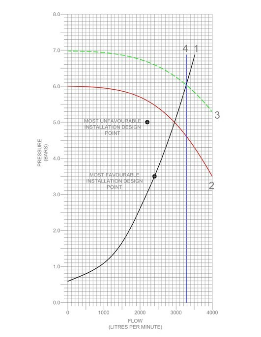
The graph illustrates four key lines:
- Black Line (1) – The system demand is derived from the pressure-flow relationship of the most favourable area of operation. It is drawn using a hydraulic quadratic formula.
This equation helps draw a curve that simulates how the system responds when only the closest sprinklers operate. Since these require less pressure to achieve the required flow, this becomes a conservative estimate for maximum system capacity. - Red Line (2) – The true pump performance curve. This line shows how the pump’s pressure output decreases as flow increases. Under BS EN 12845, the pump must provide a pressure at least 0.5 bar greater than the pressure required at the most unfavourable location to allow for changes to the design during the installation process.
- Green Line (3) – This represents the pump curve plus static pressure. The static pressure comes from the height of water in the storage tank, which contributes additional force through gravity. The green line essentially reflects the total available pressure at the pump outlet, combining both pump energy and gravitational pressure.
- Blue Line (4) – This is the Qmax line.
Qmax
Once the system demand curve (Black line 1) intersects with the pump plus static pressure curve (Green Line 3), the intersection point projects horizontally to the x-axis. This horizontal projection is known as Qmax – the maximum theoretical flow the system could deliver under the most favourable conditions.
In practical terms, Qmax represents the maximum flow demand the fire protection system must be able to supply. It reflects the worst-case scenario of flow in a sprinkler activation and forms the basis for water storage sizing.
Sizing the Sprinkler Tank
After Qmax is determined, the next step is to size the water storage tank. The volume of water required depends on both Qmax and the required duration of sprinkler operation, which again depends on the hazard class.
For example, Ordinary Hazard requires 60 minutes water supply duration.
The formula for tank sizing is:
- Tank Volume = Qmax × Duration
For example, if Qmax is calculated as 2,800 l/min for an Ordinary Hazard system, the minimum effective capacity of the tank would be:
- 2,800 l/min × 60 min= 168,000 litres minimum effective capacity for the tank
The designer would then coordinate with a sprinkler tank manufacturer to select a tank with an effective capacity equal to or greater than this volume, factoring in allowances for any dead water that cannot be used within the tank and an air gap to prevent any backflow to the town’s main infill supply.
Conclusion
Understanding and calculating Qmax is a vital step in the hydraulic design of sprinkler systems governed by codes like BS EN 12845. It provides the critical link between the fire pump, piping network and water storage, ensuring that the system can meet the worst-case flow demand during a fire.
By accurately determining Qmax, designers ensure that the system has sufficient capacity to meet immediate suppression needs and sustain performance over the full design duration. A well-calculated Qmax ensures compliance, safety and operational readiness – fundamental goals in any fire protection strategy.
Whether you're a fire protection engineer, designer or building services consultant, understanding the principles behind Qmax gives you a more comprehensive view of sprinkler system performance and helps you design systems that protect both people and property when it matters most.
Jensen Hughes’ team of experts can guide you through the process of sprinkler design development for compliant and accurately sized system unique to your project. Our team will work closely with you to understand your requirements and develop a tailored solution that best suits your needs. Find out more about our sprinkler design services here.

Andrew is a highly experienced Senior Engineer specializing in Fire Protection Systems with expertise in fire sprinkler systems design. He has a strong foundation with industry standards and compliance. Andrew has extensive experience…
Related Insights