Emergency Relief System Design
Empirical Determination of Safety Relevant Design Parameters through Adiabatic Reaction Calorimetry Testing
This article is a translation of the article by Jens Conzen, Associate Director, that appeared in Wiley-VCH CITplus Edition 7-8, 2019. It describes how to design emergency relief systems for reactive processes.
A good understanding of the thermal safety of all substances is required when storing or producing materials by chemical reaction on the factory scale. If this is not the case, deviation from normal plant operation parameters could lead to dangerous consequences for plant workers and the environment. Therefore, the correct design of pressure relief devices (e.g. pressure relief valve and / or rupture disc) is of great importance to protect chemical reactors or storage tanks against overpressure. In cases of a thermal runaway reaction, abrupt increases of temperature and pressure can occur. Special attention should be paid to reactive substances. The protection principle is simple: Limit the vessel pressure below the failure point with venting (i.e. discharge of gaseous or multiphase effluent).
The Chemical Reactivity Worksheet published by the American Institute of Chemical Engineers (AIChE) or similar resources aid in identification and control of exothermic chemical reactions. The thermal stability of substances can be analyzed in the laboratory for both normal and abnormal operating conditions.
Lessons learned from the past
One can look at numerous examples in the past where inadequate understanding or misinterpretation of data have caused accidents. Several industry incidents have demonstrated the importance of proper maintenance and engineering design of safety systems. In 2017, the explosion of an intermediate bulk storage tank for crude methylene diphenyl isocyanate (MDI) demonstrated how devastating uncontrolled events can be. The post-accident investigation concluded that a valve was either damaged or not fully closed, which allowed for leakage of a catalyst into the tank. This caused self-polymerization at a high temperature and the generation of carbon dioxide gas. The effluent formed by the self-polymerization clogged the relief line, preventing tank depressurization. Eventually, the rising pressure caused by the increased carbon dioxide gas generation resulted in an explosion. While each incident presents learning opportunities, isolated incidents are still occurring worldwide.
How to determine safety related design parameters?
Upset scenarios can be safely simulated in a bench scale adiabatic reaction calorimeter. The data can be used to design the emergency relief system (ERS). Possible hazards and triggering events are typically identified in a process hazard analysis (PHA) and may include the following:
- Fire exposure
- Loss of cooling
- Loss of agitation (e.g. formation of thermal layers causing a runaway reaction)
- Mischarge of reactants (e.g. inadvertent feed of catalyst or water)
- Batch contamination
Simulation of large-scale technical reactions
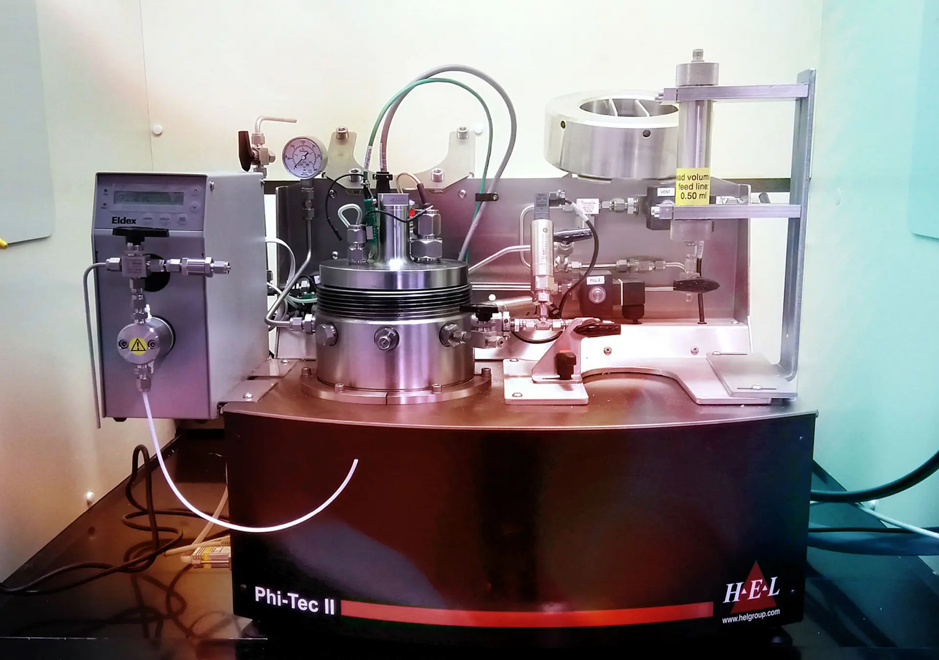
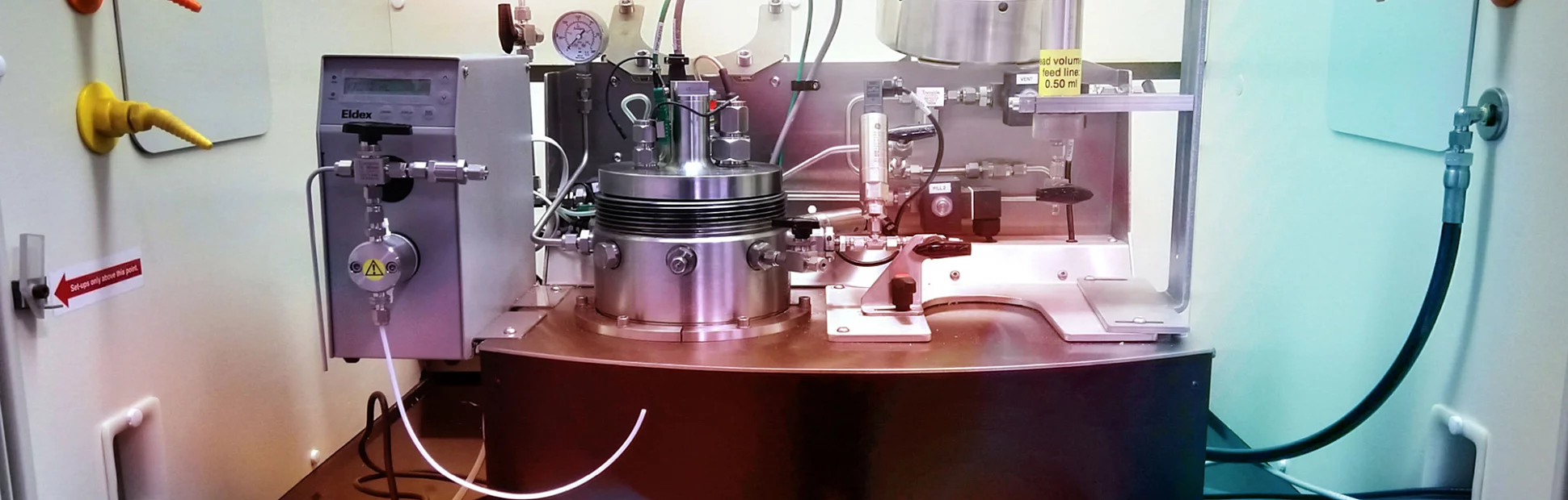
Various commercially available adiabatic reaction calorimeters can simulate large-scale chemical reactions using relatively little sample material (10-100 ml). Jensen Hughes mainly relies on the PHI-TEC II in its in-house process safety laboratory. This apparatus uses a thin-walled test cell with low thermal inertia. The test method is nearly adiabatic, by ensuring that the heat capacity of the test cell is much smaller than the heat capacity of the test sample, as is typical for full-scale industrial applications. (A high thermal inertia test would not be representative and does not yield conservative test results.) Additionally, the internal sample heat generated during the test is continuously measured and heat is applied to the outside of the test cell through heating elements to further approach near-adiabatic test conditions. The pressure inside the test cell is also tracked and balanced from the outside with nitrogen gas in the secondary containment of the test device. The test apparatus can also be used to analyze mischarges or batch contaminations by utilizing various injection pumps than can feed these materials during the experiment and even at high pressures. In addition, the flow regime (e.g. single-phase / two-phase) can be determined, which is an important parameter in the emergency relief system design. Finally, the obtained process parameters can then be applied at the plant scale without additional manipulation or scaling.
Meaningful test strategy
The success and safe operation of a series of calorimetric trials depends on a robust and meaningful test strategy. One must differentiate between three reaction types:
- Vapor systems: These are steam-like systems in which the overpressure is analogous to the vapor pressure and boiling of solvent takes place. The reaction temperature can be controlled by venting.
- Gassy systems: These systems form non-condensable gases and the reaction cannot be controlled by venting
- Hybrid systems: A combination of the first two reaction types and where cooling by boiling of solvent takes place at the set pressure of the pressure relief device.
Depending on the expected reaction type, an open or a closed test cell is specified. Vapor systems can be typically analyzed in a closed test cell. An open test cell may be beneficial to measure the temperature and pressure rise rates at the set pressure of the pressure relief device for gassy and hybrid systems. If no previous knowledge is available and it is not possible to make a good assumption on the expected reaction type, it is usually best to first test with an open test cell to perform the test as efficiently and safely as possible. The obtained kinetic parameters can then be used to design the emergency relief system according to ISO-4126-10 (standard on safety devices for protection against excessive overpressure) or according to the DIERS method (Design Institute for Emergency Relief Systems, a division of AIChE).
Pipeline reaction forces
The opening of a pressure relief valve or a rupture disk can take place in a few milliseconds. The sudden opening of the pressure relief device during an overpressure event causes the chemical effluent to accelerate through the emergency relief system. The effluent is either transported to a catch tank (closed system) or is vented into the environment (open system), depending on requirements for toxicity and flammability. The momentum change of the impulse generates temporary fluid force imbalances on the pipeline of the emergency relief system. These dynamic loads must be analyzed and combined with all static loads such as thermal and live loads in the structural design. This is particularly important for closed systems (for further discussion on this topic, reference API Publication 520 and ASME B31.3).
In addition, the pressure distribution along the pipeline is of importance. If additional vessels are connected to the same emergency relief system header, potential backpressures could fail rupture disks in reverse or prevent safety relief valves from opening at their set pressures. Hence, the transient pressure distribution in the entire emergency relief system should be simulated and compared against the maximum allowable working pressures (MAWP) of connected vessels as well as their relief devices. Various software programs can be used to model the fluid dynamics of the piping network. A simplified one-dimensional solution approach is typically adequate.
Dynamic stress analysis
A dynamic stress analysis should be performed with a structural analysis code (e.g. finite element analysis) and by considering the transient fluid forces. The various load cases to be analyzed are dictated by the local requirements (e.g. ASME B31.3 in the United States). In the past, the industry established a dynamic load factor of 2 as common practice. This factor was typically used in a simple static calculation to avoid a detailed dynamic stress analysis. However, this approach will not adequately address all plausible scenarios. The reason is that during the sudden opening of the pressure relief device, large reaction forces and bending stresses can occur at load-bearing points and pipe spans. If the dynamics of the reaction force excite natural frequencies of the pipeline, large dynamic stresses will occur. In such cases, the dynamic stress can be multiple times higher than the static stress. Therefore, a dynamic stress analysis is recommended for rapid depressurization transient scenarios.
A complete emergency relief design also includes a dispersion calculation with validation of the catch tank stack height. The dispersion calculation will compute the size of the exhaust plume as well as the potential for toxicity and ignitability. The process data obtained from the calorimetric trials as well as fluid dynamic calculations can be used as input for the dispersion model.
Summary
Many factors should be considered in protecting reactive chemistry systems from the effects of overpressure, including a fundamental understanding of normal and abnormal operating conditions, sizing of relief systems, and evaluation of dynamic forces on the piping network. Only by comprehensively evaluating these factors can an owner reliably demonstrate a credible basis for safety that will protect employees, business continuity and the environment.
Related Insights

Articles